This guide explains how to evaluate and use the Extech EX800 series of clamp meters for electrical inspection, troubleshooting, and maintenance. The EX800 designation is associated with professional clamp-meter instruments, while exact capabilities can vary by model suffix and regional package. Readers will learn how clamp measurement works, which specifications matter, how to verify readings safely, how the series compares with conventional multimeters, and what to confirm before purchase or field deployment.
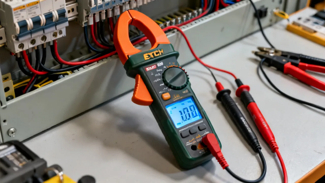
The Extech EX800 is best understood as part of a family of clamp meters rather than as a single universally identical instrument. Extech has used the EX800 designation across related electrical test products, and the exact functions, measurement ranges, accessories, display features, and safety markings may depend on the complete model number. Before purchasing or applying a meter to a live circuit, an electrician or maintenance technician should confirm the precise suffix, the current and voltage ratings, the measurement category, the included leads, the battery requirements, and the instructions supplied with that specific model.
The central purpose of an EX800-series clamp meter is to measure electrical current by placing a hinged jaw around a conductor. This method allows the user to assess current without disconnecting the conductor or inserting the meter in series with the circuit. That advantage makes a clamp meter particularly useful for motor diagnostics, load surveys, panel inspections, HVAC maintenance, generator checks, battery systems, and general electrical troubleshooting.
However, convenience should not be confused with unlimited capability. A clamp meter is only as reliable as its measurement method, operating condition, installation environment, and user technique. Current readings can be affected by multiple conductors inside the jaw, nearby magnetic fields, conductor position, waveform characteristics, low-current sensitivity, battery condition, and the meter’s selected function. An experienced technician therefore evaluates the instrument and the measurement context together.
The very important practical conclusions are these:
In product searches, the phrase “Extech EX800” may refer to the EX800 family or to a particular model within that family. This distinction matters because similar-looking clamp meters can differ in current type, maximum range, jaw size, auxiliary functions, display behavior, measurement category, and protection design. A product page, dealer listing, or used-equipment advertisement may shorten the name, while the instrument’s label and manual provide the more reliable identification.
Professionals should record the complete model number from the front panel, rear label, packaging, or calibration certificate. If the label is worn, compare the control layout and specification panel with the manufacturer’s documentation. Do not assume that a feature shown on one EX800-series model is included on every related instrument. A model that measures AC current may not necessarily measure DC current, and a meter with a broad current range may not offer the resolution needed for low-current troubleshooting.
The family concept is useful because it indicates the general category: a handheld clamp meter designed to combine current measurement with conventional multimeter functions. Yet a purchasing decision should be based on the specific device rather than on the family name alone. The following details deserve confirmation:
For inventory control, it is sensible to record the meter’s model, serial number, date acquired, last verification date, and assigned department. Two meters that appear identical may have different histories, and a clear identification system prevents technicians from applying the wrong manual or calibration record.
A conventional multimeter measures current by becoming part of the circuit. The circuit must be opened, the test leads connected to the correct current terminals, and the meter inserted in series. A clamp meter uses a different method. Its jaw senses the magnetic field generated by current flowing through a conductor.
When the jaw surrounds a single conductor, the instrument can calculate the current associated with the magnetic field. The user does not need to disconnect the conductor for a normal clamp-current measurement. This is particularly useful when testing a motor feeder, checking the load on a branch circuit, or comparing the current on several phases.
If the jaw surrounds both the outgoing and returning conductors of a two-wire circuit, their magnetic fields may largely cancel. The display may therefore show a very low value even though substantial current is flowing in the circuit. This principle is useful when checking leakage or imbalance with a suitable instrument, but it produces an incorrect result if the objective is ordinary load-current measurement.
For the most dependable reading, center the conductor in the jaw, close the jaw fully, keep the meter steady, and avoid placing other energized conductors inside the measurement area. In three-phase systems, measure one phase at a time unless a specific diagnostic procedure requires another arrangement. If a cable contains several conductors, identify each conductor before opening the jaw rather than guessing from its apparent position.
The clamp sensor does not directly tell the user whether current is flowing in the direction expected by the equipment design. On some DC-capable meters, polarity or directional information may be displayed, but the user must follow the model-specific instructions. A negative sign on a DC reading may indicate reversed orientation rather than a fault. For AC, the direction of jaw placement normally does not affect the magnitude reading, although the physical arrangement can still influence access and safety.
The first specification is the type of current the meter can measure. AC current changes direction periodically, while DC current maintains a substantially constant direction. Some clamp meters measure only AC current; others include a Hall-effect sensor or related technology for DC measurement as well. If the work involves batteries, photovoltaic systems, vehicle electrical systems, control circuits, or uninterruptible power supplies, DC capability may be essential.
Maximum current is only part of the question. Resolution and accuracy near the expected operating point are equally important. A meter designed for high-current distribution work may not provide the best sensitivity for small control currents. Conversely, an instrument optimized for low-current troubleshooting may not be suitable for a large industrial feeder. Compare the expected current with the meter’s published range and accuracy statement rather than selecting a device solely because its maximum rating appears high.
It is also important to distinguish between continuous current capability and short-duration overload capability. Some specifications describe a maximum current that can be measured for a limited time, while others refer to an input protection limit. Those are not the same thing. If a circuit may produce high inrush current, fault current, or repetitive starting surges, consult the manual before testing.
The jaw opening determines what can physically be measured. A compact jaw may suit individual conductors in a residential or light-commercial panel, while a larger cable, busbar, or bundled conductor may require a different design. Measure the actual conductor diameter and consider insulation thickness, flexible conduit access, and the available working space around the panel.
Jaw geometry also affects usability. A technician may encounter crowded cabinets where a meter can technically fit but cannot be positioned without excessive force or awkward hand movement. A practical inspection should consider whether the jaw can be opened and closed without disturbing adjacent conductors. If the operator must twist the wrist or lean into the cabinet to hold the meter, the measurement may introduce unnecessary safety risk.
Never force the jaw around an oversized conductor. Mechanical damage to the hinge or magnetic surfaces can affect subsequent readings, and forcing the instrument can shift nearby wiring. If access is restricted, use a meter with a more suitable jaw, an approved flexible current probe, or a de-energized method that meets the site’s safety procedure.
Many clamp meters also function as digital multimeters. Their voltage input specification and safety category must be reviewed independently of the current-jaw specification. The maximum current that can be measured through the jaw does not determine the safe voltage that may be applied to the test leads.
For voltage measurement, use the correct terminals, select the appropriate function, and verify the expected range before contact. Test leads should be fully insulated, undamaged, and rated for the environment. On meters with separate current terminals, leaving a lead in a current input while attempting voltage measurement can create a serious hazard because the current input may have a low-impedance path or a different fuse arrangement.
Some meters use an automatic input warning or audible reminder, but the user must not depend on that feature. Before each voltage test, visually check the lead position and the selector setting. After completing current measurements through a dedicated current terminal, return the lead to the common or voltage terminal when appropriate.
CAT markings describe the type of transient environment for which a measuring instrument is designed. CAT II generally relates to loads and receptacle-connected equipment, CAT III to distribution-level installations, and CAT IV to the origin of an installation and outdoor service connections. These categories are not interchangeable with the meter’s voltage number.
An instrument marked for a particular category must be used within the conditions stated by the manufacturer. The category depends on the entire measurement system, including the meter, leads, probes, accessories, and the user’s method. A highly rated meter does not make an unsafe procedure acceptable. An accessory with a lower rating can reduce the safety of the complete setup.
When working in industrial panels, service entrances, switchgear, motor-control centers, or outdoor distribution equipment, determine the prospective transient environment before selecting a meter. If the site’s electrical safety program requires a particular category and voltage combination, that requirement should control the selection.
A clear display is valuable in panels where lighting is limited or the user must stand at an angle. Backlighting, data hold, minimum or maximum recording, relative mode, and automatic range selection can improve workflow, but they can also conceal an important detail: a held value may no longer represent the present circuit condition.
Data hold should be used deliberately. Before recording a result, identify whether the display is showing a live measurement, a held value, a peak value, or a recorded minimum or maximum. When a circuit changes rapidly, note the operating state and the selected function alongside the reading. If several technicians use the same meter, make sure everyone understands the indicator symbols used by that model.
Automatic ranging can be convenient for general inspection, while manual ranging may provide a steadier display when the expected signal is known. A reading near the boundary between ranges may appear to change resolution or update speed. This is normal for many instruments, but the user should recognize the behavior before comparing measurements taken under different settings.
Motors, transformers, compressors, lighting equipment, and power supplies may draw a starting current that differs substantially from their normal operating current. If the specific EX800 model includes an inrush or peak-related function, consult its manual for the measurement window and operating procedure. Such a function should not be assumed merely because the meter is described as a professional clamp meter.
Even when an inrush function is available, the result depends on the switching event, the supply impedance, the load condition, and the instrument’s response characteristics. Record whether the motor was cold or warm, loaded or unloaded, and started normally or under an unusual condition. A high starting value alone does not prove that the motor or protection system is defective.
For motor inspection, measure each phase under the same operating condition and compare the readings with the equipment documentation and the site’s maintenance history. A difference between phases may indicate an unbalanced supply, unequal loading, connection problems, or a motor issue, but the clamp reading alone does not identify the cause.
Before measuring, identify the motor nameplate information, rated voltage, rated current, connection type, and expected load. Take readings after the motor reaches a stable operating state, then note any unusual sound, temperature, vibration, or starting behavior. If the current changes cyclically, use a recording function or repeat measurements at defined intervals.
Compare current readings with the motor’s actual mechanical load. A lightly loaded motor may draw substantially less than its nameplate current, while a motor under severe mechanical load may approach or exceed its rated value. A reading should not be judged without knowing whether the equipment was operating at idle, partial load, or full production demand.
Never open a motor terminal box or remove a protective cover solely to obtain a reading unless the work is authorized and the circuit has been made safe according to the applicable procedure. A clamp measurement should reduce unnecessary circuit disturbance, not encourage exposure to energized parts.
Technicians often use clamp meters to evaluate compressors, fans, pumps, heaters, and control circuits. The reading should be interpreted alongside supply voltage, equipment operating mode, ambient conditions, and manufacturer data. A compressor current can vary with pressure, temperature, refrigerant conditions, and start-up state.
When measuring an HVAC system, confirm whether the conductor carries the compressor load, a crankcase heater, a fan motor, or another circuit. In crowded disconnects, make sure the jaw surrounds only the intended conductor. If the equipment uses electronic controls or variable-frequency operation, check whether the meter’s current measurement method is suitable for the waveform.
A useful HVAC record may include suction and discharge conditions, outdoor temperature, indoor demand, compressor status, fan status, and the current on each relevant conductor. Current that appears high during a hot afternoon may be normal for the operating condition, while the same current during mild weather may deserve investigation.
In commercial buildings, an EX800-series clamp meter can support load surveys, circuit identification, and preventive maintenance. A technician may compare current among distribution phases, check whether a newly installed load is operating, or investigate a breaker that trips during peak activity.
These tasks require context. A current reading taken while a building is unoccupied may not represent the load during production, kitchen operation, elevator use, or climate-control demand. A useful report records the date, time, equipment state, measured phase, meter function, and environmental conditions where relevant.
When comparing phases, measure them as close together in time as possible. Variable loads can change between measurements and create an apparent imbalance that is actually a timing difference. For larger facilities, repeat the survey during several operating periods and compare the results with demand data from the building-management or energy-monitoring system.
Where the particular EX800 model supports DC current measurement, it may assist with battery, charging, starter, or auxiliary-load checks. The user must confirm that the current range, jaw design, and accuracy are appropriate for the vehicle or battery system. The meter should not be placed around conductors carrying more current than the published limit.
For low-current parasitic drain investigations, a general-purpose clamp meter may not provide sufficient resolution. A specialized low-current clamp accessory or an appropriately configured multimeter may be more suitable. Disconnecting a vehicle battery can also reset control modules or alter the condition being investigated, so the test plan should account for that possibility.
DC clamp meters may require zeroing before measurement. Nearby magnetic fields, residual magnetism, and the orientation of the conductor can influence the result. Follow the model-specific zero procedure and repeat the zero check if the meter is moved or the ambient magnetic environment changes.
DC clamp measurement can be useful for checking battery banks, photovoltaic strings, charge controllers, and inverter connections when the selected meter is approved for the voltage and current involved. Photovoltaic systems present a particular hazard because sunlight can keep conductors energized. The absence of an obvious switching sound or moving machinery does not indicate that a conductor is de-energized.
Use the installation’s isolation procedure, observe polarity where applicable, and confirm that the meter and leads are rated for the system. When comparing strings, keep irradiance and operating conditions in mind. A difference may result from shading, orientation, connector resistance, module condition, or inverter behavior, and requires further investigation.
Battery banks can deliver extremely high fault current even when their nominal voltage appears modest. Avoid creating a short circuit with probes, jewelry, tools, or damaged accessories. The clamp method is often preferable because it can measure current without placing the meter in series, but the surrounding battery terminals and conductors remain hazardous.
This process is intentionally conservative. A fast reading is not necessarily a useful reading. The value of a clamp meter lies in producing a measurement that can be repeated, explained, and compared with a known reference or an engineering expectation.
When taking multiple readings, keep the measurement geometry consistent. If the first phase is measured with the conductor centered and the second phase is measured near the jaw edge, the difference may partly reflect technique. Consistency is especially important when evaluating small phase imbalances or comparing results over time.
| Observed problem | Likely cause | Recommended response |
|---|---|---|
| Very low current on a known load | Both outgoing and returning conductors are inside the jaw | Reposition the jaw around one conductor only |
| Unstable display | Changing load, electrical noise, poor jaw closure, or unsuitable waveform | Repeat the test under stable conditions and consult the model manual |
| Unexpected zero on DC current | Incorrect function, missing zero adjustment, reversed procedure, or current below resolution | Select the correct function and follow the model-specific zeroing instructions |
| Reading differs between technicians | Different conductor position, timing, range, or load state | Standardize the measurement position and operating condition |
| Display remains unchanged after circuit adjustment | Data hold or recording mode is active | Exit the hold or recording function and repeat the reading |
| Meter cannot fit around the conductor | Jaw opening is too small or access is restricted | Use a compatible instrument or an approved flexible current sensor |
| Reading is higher than expected near switchgear | Magnetic influence from nearby high-current conductors or busbars | Reposition the meter and compare with another suitable method |
| DC reading drifts after the meter is moved | Magnetic field changes, residual magnetism, or zero offset | Repeat the zero procedure and maintain a consistent orientation |
The conductor’s position inside the jaw can influence accuracy, especially when the conductor is close to one side or when the instrument is near other magnetic fields. Centering the conductor is a sound general practice, but it does not replace the manufacturer’s accuracy guidance.
Keep the jaw clean and ensure that its mating surfaces close fully. Dirt, damage, or a misaligned hinge can reduce the quality of the magnetic circuit. Do not force the jaw around oversized cable. Mechanical stress can damage the instrument and create an unsafe working condition.
Nearby high-current conductors, transformers, contactors, and busbars may affect a sensitive current measurement. If a result seems implausible, move the meter away from the suspected source, reposition the conductor, and repeat the test. Compare the result with a second suitable instrument when the decision has safety, production, or compliance consequences.
Do not use the jaw as a mechanical lever or attempt to separate tightly packed conductors with it. The jaw is a sensing component, not a cable-management tool. In a crowded enclosure, de-energize and rearrange the conductors only under an approved procedure, or select an instrument specifically designed for the access challenge.
Modern electrical systems frequently contain switching power supplies, LED drivers, rectifiers, battery chargers, and variable-frequency drives. These devices can draw nonsinusoidal current. The accuracy of a clamp meter may depend on whether it uses an average-responding method or true-RMS technology, as well as on the crest factor and frequency of the measured signal.
A true-RMS instrument generally provides a more meaningful result for many distorted waveforms, but the designation does not guarantee accurate measurement under every condition. The published specifications define the applicable frequency range, crest-factor limitations, and accuracy conditions. If the EX800 model under consideration is used around electronic loads, read those sections carefully.
A reading from a nonlinear load may be numerically correct within the meter’s stated limitations but still not answer the engineering question. For example, a power-quality investigation may require peak current, harmonic content, phase relationship, or neutral-current analysis rather than a single RMS value.
When diagnosing a drive-fed motor, the current waveform at the drive output may differ from the waveform on the input side. A general clamp meter reading may be useful for trend comparison but may not replace a drive-compatible analyzer or oscilloscope when waveform quality is central to the investigation. Avoid connecting ordinary test equipment to a drive output unless the equipment is specifically rated and approved for that application.
Electrical measurement should be performed only by a person trained for the voltage and installation environment involved. The Extech EX800 does not remove the need for lockout and tagout, arc-flash assessment, insulated tools, appropriate personal protective equipment, or local electrical safety procedures.
Before making contact with a circuit, determine whether the measurement can be completed in a de-energized state. If the circuit must remain energized, establish boundaries, use suitable PPE, remove conductive jewelry, maintain stable footing, and keep the instrument and leads under control. Do not work alone where the site rules or risk assessment require a second qualified person.
Important safety conditions include:
A clamp meter can reduce the need to break into a circuit, but it does not make an energized panel harmless. The jaw and the instrument body may be insulated, while the surrounding installation remains capable of producing shock, arc flash, burns, or equipment damage.
When measuring in a panel, plan the hand position before approaching the conductors. Avoid placing the body directly in front of an energized opening, and do not reach across exposed energized parts. If the measurement requires an unstable stance, excessive force, or contact with adjacent components, stop and choose a safer method.
Accuracy specifications are normally stated under controlled conditions. Field performance can be influenced by temperature, humidity, battery condition, conductor placement, electromagnetic interference, and the characteristics of the measured signal. A displayed value should therefore be treated as a measurement with uncertainty, not as an absolute fact.
For routine maintenance, a basic functional check may involve comparing the EX800 with a known source or a recently verified instrument. This does not constitute a formal calibration. Where measurements support compliance, product release, energy billing, protection settings, or contractual decisions, use a documented calibration process appropriate to the organization’s quality requirements.
Calibration intervals should be determined by the manufacturer’s guidance, organizational policy, usage frequency, environmental exposure, and the consequences of an incorrect result. Instruments used daily in harsh industrial conditions may require more frequent verification than those used occasionally in a controlled workshop.
Keep records that identify the instrument, serial number, calibration date, reference standard, observed result, technician, and any corrective action. If a meter fails verification, quarantine it until it has been assessed. Do not compensate for a questionable instrument by mentally adjusting every reading.
Verification after a drop, overload, contamination event, or exposure to extreme temperature is prudent even if the normal calibration date has not arrived. A meter can continue to display numbers after internal damage, so a functioning screen is not evidence that the instrument remains accurate or safe.
Low battery indications can affect operation, display visibility, and confidence in a measurement. Replace batteries according to the manual and use the specified type. Remove batteries before long-term storage when the manufacturer recommends it, particularly where leakage could damage the instrument.
Clean the housing with a method approved by the manufacturer. Avoid solvents, abrasive materials, and excessive moisture. The jaw should close smoothly without sticking. If the instrument has a temperature probe or specialized accessory, inspect its connector and insulation before use.
Store the EX800 in a protective case or a clean, dry location away from extreme heat, corrosive chemicals, heavy vibration, and strong magnetic sources. Do not place heavy tools on the meter. A small crack or distorted jaw may not be obvious during a quick inspection but can affect safety and measurement performance.
Do not attempt unauthorized repairs inside the meter. Internal fuses, barriers, insulation, and protective components are part of the safety design. If the meter has been subjected to an overload, liquid exposure, or physical impact, have it examined by a qualified service provider or replace it according to the organization’s equipment policy.
| Requirement | Clamp meter advantage | When a conventional multimeter may be preferable |
|---|---|---|
| Measuring load current without opening a conductor | Jaw measurement reduces circuit interruption | Not usually necessary if current is already available at a safe test point |
| High-current equipment inspection | Designed to surround a conductor rather than carry the full load through input terminals | A dedicated power analyzer may be better for detailed waveform or energy studies |
| Small electronic signals | Useful only if the selected clamp model provides suitable resolution | A bench or handheld multimeter may offer better low-level accuracy |
| Voltage, resistance, and continuity testing | Many clamp meters include these functions | A standard multimeter may provide a larger display or more specialized ranges |
| Flexible access around large conductors | A large jaw or compatible current probe can improve access | A fixed-jaw meter may be impractical in confined spaces |
| Detailed electrical quality analysis | Suitable for basic current checks and trends, depending on model | A power-quality analyzer may be required for harmonics, transients, and energy parameters |
The choice is not necessarily either-or. Electrical teams often use a clamp meter for rapid current checks and a conventional multimeter, insulation tester, phase-rotation meter, or power analyzer for a more complete diagnosis. The instrument should match the question being asked.
A standard multimeter may be more convenient for measuring small DC voltage drops, sensor outputs, resistance, and continuity. An insulation resistance tester is needed when the question concerns insulation quality rather than operating current. A thermal camera may reveal overheating that current measurements alone cannot explain. The EX800 is valuable because it fills a particular role, not because it replaces every other diagnostic tool.
When evaluating an EX800 listing, begin with identity rather than price. Confirm the exact model number, manufacturer documentation, condition, accessories, and warranty terms. A lower purchase price may not represent good value if the instrument lacks suitable leads, has an uncertain calibration history, or does not meet the required safety category.
New equipment should arrive with an identifiable model label and documentation. For used equipment, ask for clear photographs of the front, rear label, jaw, terminals, and display. Check whether the battery compartment is clean and whether the jaw closes evenly. If the seller cannot establish the model or provide credible specifications, treat the product as unsuitable for critical measurement work.
Compare the following before placing an order:
Specifications should be taken from the manufacturer’s current manual or datasheet for the exact model. Retailer summaries can omit measurement conditions or combine details from neighboring products. For a professional purchase, retain a copy of the documentation used for approval so future users know which limits apply.
Consider the total cost of ownership. A meter may require replacement leads, a protective case, calibration, batteries, or specialized accessories. If several technicians will use it, durability and service support may matter more than a minor difference in purchase price. For a facility with strict maintenance records, a model supported by accessible calibration and repair services can be more practical than an inexpensive but poorly documented alternative.
A single number rarely explains an electrical problem. An expert looks for relationships: current compared with rated load, phase-to-phase balance, change over time, temperature, voltage, and equipment behavior. The EX800 can provide an important observation, but diagnosis depends on the complete evidence.
For example, an unexpectedly high motor current might result from mechanical overload, low supply voltage, phase imbalance, bearing problems, incorrect connection, or a measurement taken during acceleration. A low reading might indicate an unloaded motor, a failed phase, an open control path, or a conductor that was not correctly enclosed by the jaw. The meter does not decide among these explanations by itself.
Use a repeatable measurement plan. Take readings at the same points, under comparable loads, with the same instrument settings. If a trend is important, record several observations rather than relying on memory. Mark the instrument’s condition and calibration status in the maintenance record.
When a reading conflicts with an equipment nameplate or protection setting, stop and verify the basics: correct conductor, correct function, correct range, complete jaw closure, proper phase identification, and actual operating state. Many apparent equipment faults begin as measurement-process errors.
Measurements should also be interpreted against the equipment manufacturer’s documentation. Nameplate current is generally a rated operating reference, not a universal value that every operating condition must match. Protection-device ratings, conductor ampacity, ambient-temperature corrections, duty cycle, and motor service factor may all affect the appropriate interpretation.
A concise field record can make an EX800 measurement much more useful to the next technician. Include:
Photographs can support a report, but they should not expose confidential information or encourage unsafe documentation practices. Follow the site’s rules for photographing electrical equipment, labels, and control panels.
For trend monitoring, use consistent units and terminology. Record whether the value is an instantaneous observation, an average, a minimum, a maximum, or an inrush result. A later technician should be able to tell whether a change represents a real equipment condition or simply a different measurement mode.
| Condition or requirement | Why it matters |
|---|---|
| Qualified operator | The user must understand electrical hazards, instrument limits, and site procedures. |
| Correct model identification | EX800-series features and ratings may vary by complete model number. |
| Suitable CAT rating | The meter must be appropriate for the transient environment of the installation. |
| Undamaged meter and leads | Physical defects can compromise both protection and measurement reliability. |
| One intended conductor inside the jaw | Multiple conductors can cancel magnetic fields and produce misleading current values. |
| Stable, identified operating state | Load changes can explain differences that might otherwise be mistaken for faults. |
| Documented calibration or verification | Critical measurements require evidence that the instrument is performing acceptably. |
| Appropriate personal protective equipment | A clamp meter does not eliminate shock and arc-flash risks. |
| Correct accessories | Leads, probes, and adapters must carry ratings suitable for the complete measurement environment. |
| Suitable environmental conditions | Moisture, contamination, heat, and electromagnetic interference can affect safety and results. |
The Extech EX800 designation is associated with clamp-meter instruments used for electrical current measurement and, depending on the specific model, additional multimeter functions. Typical applications include motor maintenance, panel inspection, HVAC troubleshooting, facility maintenance, battery systems, and general electrical diagnostics. The exact function set should be confirmed from the complete model number.
That depends on the precise EX800-series model. Some clamp meters support both AC and DC current, while others are designed primarily for AC. Check the front-panel symbols and the manufacturer’s manual before measuring DC systems. Do not infer DC capability from the family name alone.
Yes, a clamp meter is designed to measure current by surrounding a conductor, so the circuit normally does not need to be opened for the current-jaw measurement. The jaw should enclose the intended single conductor and close completely. This does not remove the need for electrical safety controls around an energized installation.
The most common explanation is that the jaw surrounds both the outgoing and returning conductors, causing their magnetic fields to cancel. Other possibilities include an incorrect function, current below the meter’s resolution, an incompletely closed jaw, or a conductor that is not carrying the expected load. Recheck the setup systematically.
Only if the measurement objective is appropriate and the conductor arrangement allows it. For ordinary load current, the jaw should generally surround one current-carrying conductor. Surrounding a complete two-wire cable often produces a near-zero net reading because the currents flow in opposite directions.
No. Current capacity is only one specification. Voltage rating, CAT category, waveform compatibility, jaw opening, accuracy, frequency range, environmental limits, and lead ratings also matter. A meter with a high current range may still be unsuitable for a particular distribution system.
Usually not. A clamp meter can provide valuable current and voltage observations, but a power-quality analyzer is designed for more detailed evaluation such as harmonics, transients, dips, swells, phase relationships, and energy parameters. Use the instrument that matches the diagnostic question and the required evidence.
Begin with a visual inspection and a functional check against a known suitable source or a recently verified instrument. For formal work, use a documented calibration or verification process with traceable standards as required by the organization. If the meter fails the check, remove it from critical service until it has been evaluated.
Determine whether the load itself is changing. Then check jaw closure, conductor position, selected function, battery condition, nearby magnetic fields, and waveform characteristics. Repeat the measurement under a defined operating state. If the result remains inconsistent, compare it with another appropriate instrument and consult the model documentation.
It can be, provided the exact model, physical condition, safety markings, accessories, and calibration history are established. Inspect the jaw, hinge, terminals, display, case, battery compartment, and leads. For safety-critical work, a current calibration certificate or professional verification is preferable to an undocumented unit.
The appropriate interval depends on manufacturer guidance, usage, environment, internal quality policy, and the consequences of an incorrect measurement. High-use industrial instruments may need more frequent checks than occasionally used workshop meters. Follow the organization’s documented calibration program rather than choosing an interval solely by habit.
Only after confirming that the exact model is suitable for the waveform, frequency range, and voltage environment. Drive output can contain rapidly switching and nonsinusoidal signals that affect ordinary meter readings. For detailed drive diagnostics, a drive-compatible instrument or power analyzer may be required.
Verify the measurement arrangement before trusting the displayed value. Identify the correct conductor, confirm the function and rating, close the jaw fully, observe the equipment state, and record the conditions. This habit prevents many errors and improves the value of the measurement more than simply selecting a larger range.
No, not unless the specific manufacturer instructions explicitly authorize an unusual procedure. Resistance and continuity functions generally apply a test signal to the circuit and are intended for de-energized equipment. Applying them to an energized circuit can damage the meter, damage the equipment, or create a hazardous condition.
Conductor position, jaw alignment, nearby magnetic fields, and the load’s natural variation can all contribute. DC measurements may also be affected by orientation and zero offset. Use a consistent position, center the conductor where practical, close the jaw completely, and compare readings only when the equipment is operating under comparable conditions.
The Extech EX800 can be a practical instrument for professionals who need current measurements without routinely interrupting a circuit. Its usefulness comes from combining clamp-based current sensing with selected multimeter functions in a portable format. The series is especially valuable for maintenance rounds, equipment checks, and first-stage troubleshooting.
The correct evaluation, however, is model-specific. Buyers and users should verify the complete EX800 designation, technical specifications, safety category, accessories, and calibration requirements before placing the meter into service. During measurement, a disciplined procedure is essential: isolate whenever possible, use the correct protective measures, surround the intended conductor only, and interpret the reading in relation to the equipment and operating conditions.
Used in that manner, the EX800 is more than a convenient current indicator. It becomes part of a structured diagnostic process—one that produces repeatable observations, supports maintenance decisions, and helps technicians distinguish a genuine electrical abnormality from an error in measurement technique.
The strongest results come from treating the meter as one component of a broader professional system. Correct model identification, proper training, suitable PPE, careful measurement technique, calibration control, and accurate documentation all contribute to dependable work. When those conditions are met, an EX800-series clamp meter can provide fast, useful information while minimizing unnecessary circuit disruption.
Striking the Perfect Balance: Navigating Premiums and Out-of-Pocket Expenses in Senior Insurance Plans

Explore the Tranquil Bliss of Idyllic Rural Retreats

How to Make Lasting Memories at Disneyland Attractions

Affordable Phones and Plans for Seniors

Affordable Full Mouth Dental Implants Near You

Unlock the Top Kept Secrets to Finding Your Ideal Dentist for Flawless Dental Implant Results!

Discovering Springdale Estates

Unveiling RS Sul Telecom Services

The Guide to Car Trading

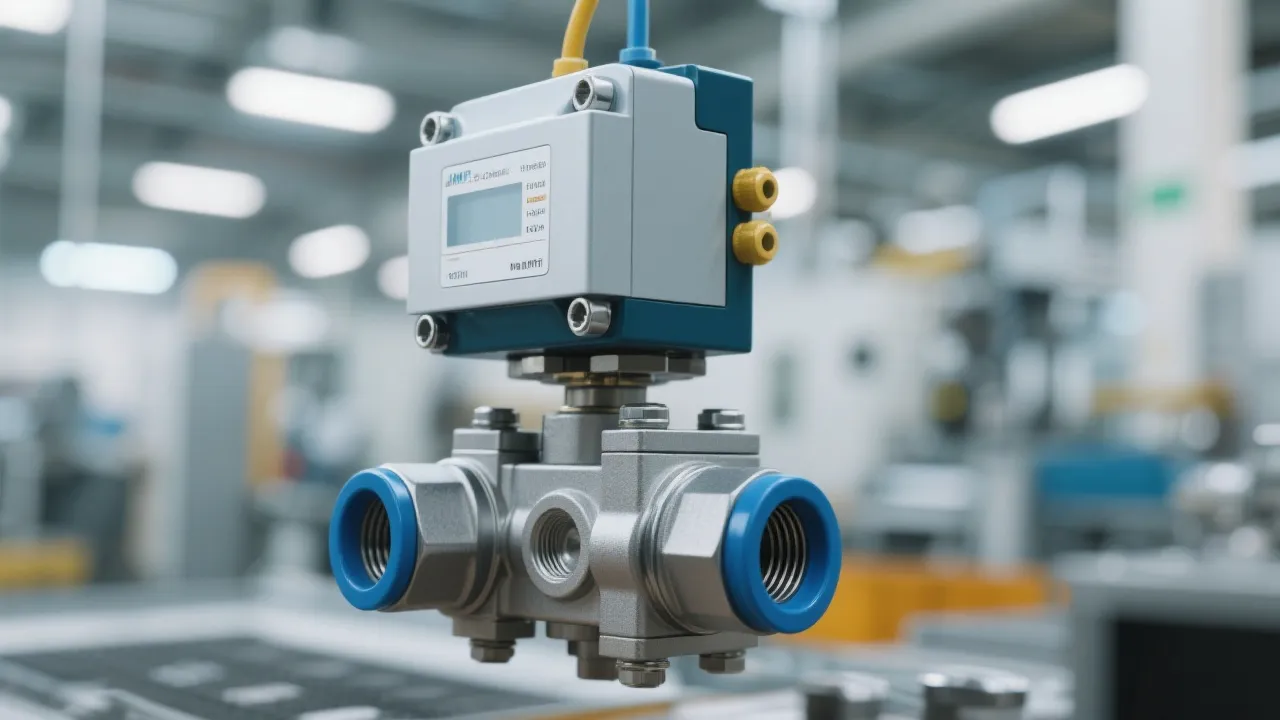
Understanding Proportional Valves
Proportional valves are hydraulic components vital for controlling fluid flow and pressure with high precision in various industrial applications. Their importance in automation and manufacturing settings stems from their ability to offer variable output in response to input signals, greatly enhancing system efficiency and performance.
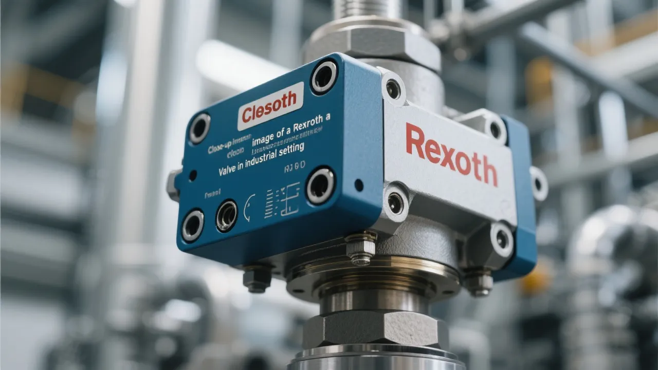
Understanding Rexroth Valve Systems
Rexroth Valves are quintessential components in various industrial applications, known for their precision and reliability. These hydraulic, pneumatic, and electrohydraulic valves regulate fluid flow in machinery, ensuring optimal performance and safety. Understanding their functionality and benefits is crucial for industries seeking efficiency and sustainability in their operations.

Unveiling Thermo Fisher Chromatography
This article explores the pivotal role of Thermo Fisher Chromatography in modern analytical science. Chromatography is crucial for separating compounds within mixtures, making it indispensable in industries such as pharmaceuticals and environmental testing. Thermo Fisher Scientific stands out in this field for its innovative solutions, leading to improved accuracy and efficiency in research and development.

Understanding Corrosion Inhibitor Manufacturers
In today's industrial landscape, corrosion inhibitor manufacturers play a crucial role in safeguarding equipment and infrastructure against corrosive damage. These manufacturers provide specialized chemicals that prevent corrosion in various environments, including industries such as oil and gas, marine, and construction. Understanding their operations and offerings is essential for selecting the right supplier and maintaining asset longevity.
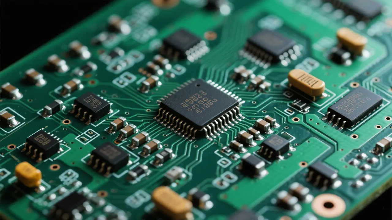
Analyzing Lm66100 Digikey Components
This article offers an in-depth analysis of the Lm66100 component available through Digikey, a renowned distributor of electronic components. The Lm66100, a load switch, is integral in industry applications, providing efficient power management. This piece explores its features, applications, and availability through Digikey, while offering a comprehensive guide for industry professionals seeking to optimize their electronic designs.

Leading Corrosion Inhibitor Suppliers
Corrosion inhibitor manufacturers play a crucial role in protecting materials from degradation. These companies specialize in creating chemical compounds that slow down or prevent the corrosive effects on various surfaces, especially metals. Understanding their production processes and solutions offered is vital for industries reliant on metal infrastructure.