This guide explains how to evaluate the Extech EX800 clamp-meter family, including its measurement role, operating principles, safety considerations, model selection factors, and practical maintenance. The EX800 designation generally refers to a group of Extech clamp meters designed for electrical troubleshooting and current measurement without disconnecting conductors. Exact functions, ranges, and accessories depend on the individual model, so the manufacturer’s documentation should be checked before purchase or use.
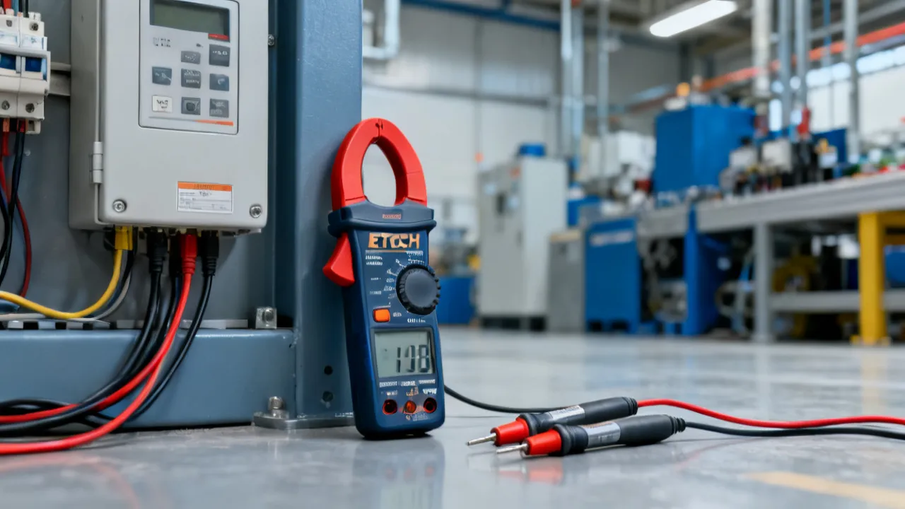
The Extech EX800 is best understood as a family designation rather than a single specification that applies to every instrument sold under the name. Within the EX800 range, individual models may differ in current capacity, temperature measurement, non-contact voltage detection, inrush-current capability, display features, data-hold functions, and accessory packages. That distinction matters because a technician selecting a clamp meter for motor commissioning may need a different configuration from an electrician performing routine distribution-board checks, while an HVAC technician may place greater value on temperature measurement and inrush capture.
At the center of the series is the clamp-meter principle: current can be measured by placing a conductor inside the meter’s jaw, allowing the user to assess electrical load without opening the circuit. This is particularly useful when working on fixed wiring, machinery, HVAC equipment, control cabinets, commercial electrical systems, and service equipment where disconnecting a conductor would be inconvenient or hazardous. Depending on the specific model, the instrument may measure alternating current, direct current, voltage, resistance, continuity, frequency, capacitance, temperature, or short-duration startup current.
From an industry perspective, the most important purchasing decision is not the product name alone. It is the relationship between the intended measurement, the electrical environment, the required accuracy, the jaw opening, the safety category, and the meter’s operating procedure. A carefully selected EX800-series instrument can be practical for field diagnostics, but it should never be treated as a substitute for electrical training, isolation procedures, appropriate personal protective equipment, or a complete diagnostic plan.
The phrase “clamp meter” also describes a broad range of instruments with substantially different capabilities. Some are intended for basic residential troubleshooting, while others are designed for demanding industrial environments. A clamp meter can be excellent for measuring feeder current but less suitable for measuring very small control currents. Similarly, an instrument with a wide jaw may fit around large conductors but provide fewer specialized functions than a smaller, more advanced model. The EX800 family should therefore be evaluated by matching its detailed specification to the job rather than by relying on a general reputation or a retailer’s abbreviated description.
Clamp meters are designed primarily to simplify current measurement. A conventional multimeter measures current by being inserted into a circuit, which can require disconnection and may create additional exposure to energized conductors. A clamp meter instead senses the magnetic field surrounding a conductor. The jaws close around the conductor, and the meter calculates the corresponding current without requiring the current path to pass through the instrument.
In an Extech EX800-series instrument, the basic workflow is usually straightforward:
Clamping around more than one conductor can produce an incorrect or near-zero reading because opposing magnetic fields may cancel. This is one of the most common errors made by inexperienced users. A clamp meter should normally surround a single current-carrying conductor when measuring load current. When checking a cable containing multiple conductors, an electrician may need access to an individual conductor or a purpose-designed current-measurement point.
Many clamp meters also include a conventional input section for voltage and resistance tests. This makes the instrument useful as a general troubleshooting tool, although its capabilities may not be identical to those of a dedicated bench or precision multimeter. The user should distinguish between functions that use the clamp sensor and functions that use test leads. Each has its own connection requirements, overload limits, and safety considerations.
Some EX800 models may also offer features such as automatic ranging, maximum or minimum recording, data hold, relative measurement, backlighting, audible continuity, or a low-battery indicator. These features can improve convenience, but they do not remove the need to verify the selected function and confirm that the displayed reading makes sense. A held value can be mistaken for a live measurement if the user does not notice that the display is frozen.
Current is a central indicator of electrical behavior. Voltage may be present even when a load is not operating correctly, while current measurement helps reveal whether a motor, heater, compressor, transformer, or power supply is drawing the expected load. The measurement does not provide a complete diagnosis by itself, but it adds important evidence.
For example, a motor that draws substantially more current than expected may have mechanical resistance, phase imbalance, bearing problems, incorrect supply conditions, or a developing winding fault. A motor drawing less current than expected may be lightly loaded, disconnected from its mechanical system, or affected by a supply or control issue. Interpretation should always be based on the equipment manufacturer’s specifications, operating state, and ambient conditions.
In building services, the Extech EX800 may be considered for tasks such as:
The instrument’s suitability depends on the precise model and its published electrical limits. A professional should review the relevant manual and product data sheet before connecting the meter to a system, particularly where high-energy industrial equipment or transient-rich circuits are involved. The user should also determine whether the circuit contains variable-frequency drives, switching power supplies, or other equipment that may produce distorted waveforms or rapid changes in current.
Current measurement can be especially valuable during preventive maintenance because it allows a technician to establish a baseline. A pump, fan, or compressor can be measured when operating normally, and future readings can be compared with that baseline. A gradual increase may suggest mechanical wear, a blocked filter, a failing bearing, or a change in process conditions. Baseline records are more useful when they include the date, ambient temperature, equipment load, supply voltage, and operating mode.
The term “Extech EX800” can refer to several related instruments. Buyers should therefore avoid assuming that every EX800 listing has identical functions. Model numbers in a product family often indicate added capabilities rather than a completely different operating concept. A model with a similar appearance may have a different current range, different internal protection, or a different measurement method.
| Selection factor | Why it matters | What to verify |
|---|---|---|
| AC current measurement | Used for many household, commercial, and industrial loads. | Maximum range, accuracy, resolution, and waveform limitations. |
| DC current measurement | Relevant to vehicles, battery systems, control circuits, and solar-related work. | Whether the selected model supports DC current and how zero adjustment is performed. |
| True RMS capability | Can improve readings on non-sinusoidal or electronically controlled loads. | Whether the specific model is True RMS and the conditions stated in its documentation. |
| Inrush measurement | Helps assess short-duration startup current from motors and similar equipment. | Inrush mode operation, capture period, trigger conditions, and current limit. |
| Temperature function | Supports equipment checks involving heating, cooling, and thermal comparison. | Probe type, temperature range, accuracy, and included accessories. |
| Non-contact voltage detection | Can provide a preliminary indication that voltage may be present. | Detection limitations and the requirement for confirmatory testing. |
| Jaw capacity | Determines whether the tool can fit around the intended cable or conductor. | Maximum jaw opening and clearance around insulated conductors. |
| Safety category | Indicates the environments for which the meter is designed when used correctly. | Published CAT rating, maximum voltage, and applicable safety standards. |
| Low-current resolution | Determines how effectively the meter can observe small control or standby currents. | Display resolution, accuracy at low levels, and minimum specified current. |
| Display and controls | A clear display and intuitive controls reduce operating errors in the field. | Backlight, display size, data hold, range selection, and readability. |
This comparison is a buying framework, not a replacement for the model-specific specification sheet. A retailer may group multiple products under an “EX800” search term, while the actual instrument supplied may be an EX810, EX820, EX830, EX840, or another related designation. The exact model printed on the meter and packaging should be recorded before ordering replacement leads or accessories.
Product revisions and regional packages can also create differences. Two listings may show the same general instrument but include different probes, cases, batteries, or language versions of the manual. The presence of a temperature jack or a special accessory should not be assumed merely because a photograph shows one. Confirm the contents of the package in writing when accessories are important to the work.
Alternating-current measurement is the most familiar clamp-meter application. The current changes direction periodically, producing a magnetic field that the clamp sensor detects. AC current is common in building distribution, motors, lighting circuits, heating equipment, and many commercial systems.
Direct-current measurement is useful for battery banks, vehicle electrical systems, industrial controls, and certain renewable-energy installations. DC clamp measurement requires additional care because the meter’s magnetic sensor can be influenced by the surrounding magnetic field and by residual magnetism in the jaws. A zero or relative function may be necessary before the conductor is clamped. The procedure should follow the manufacturer’s instructions.
When measuring DC current, the user should consider polarity, conductor orientation, and the possibility that a reading may drift if the meter is moved or the jaw is not fully closed. A stable mechanical position and a properly zeroed meter improve repeatability. If the measured value seems inconsistent with the system design, the user should repeat the test and compare it with an independent measurement method where appropriate.
AC and DC measurements also differ in the way the instrument responds to external conditions. AC readings may be affected by nearby energized conductors, particularly when conductors are close together or the measured current is low. DC readings may be affected by the Earth’s magnetic field, the orientation of the meter, and residual magnetism. These effects are not necessarily evidence of a defective instrument, but they should be recognized when a reading is near zero or when high precision is expected.
When measuring three-phase equipment, each phase should be measured individually under comparable conditions. The technician should record the supply voltage, motor load, and phase current. A small difference can be normal depending on the equipment and load, while a pronounced imbalance may warrant further investigation. Current imbalance should not be interpreted without checking voltage imbalance and the possibility of unequal mechanical loading.
Many modern electrical loads do not draw a smooth sine-wave current. Variable-frequency drives, switch-mode power supplies, LED drivers, battery chargers, computers, and electronic controls can create distorted waveforms. An average-responding meter may display a value that differs from the effective heating value of such a waveform.
True RMS measurement is intended to provide a more meaningful result for AC signals that are not purely sinusoidal, provided the waveform remains within the meter’s stated bandwidth and crest-factor limits. This does not mean that every True RMS reading is automatically accurate under every condition. The user must still observe the specified frequency range, current range, and measurement environment.
For technicians evaluating an Extech EX800, True RMS status should be confirmed for the exact model rather than assumed from the family name. If work involves electronic power conversion or heavily distorted loads, this feature may be more important than a larger maximum current number. Conversely, for straightforward resistive loads, other factors such as safety rating, display readability, jaw size, and durability may have greater practical value.
Waveform distortion can also make two meters display different values even when both are operating correctly. One instrument may be average responding, another may be True RMS, and a third may have a wider bandwidth or different crest-factor performance. When comparing readings, the instruments should use comparable measurement methods. A technician should also avoid assuming that a True RMS meter can measure high-frequency or rapidly changing signals beyond its published specifications.
Electronic loads often change their operating mode. For instance, a variable-speed drive may draw different current as the motor accelerates, while a battery charger may reduce current as the battery approaches its target voltage. In these situations, the measurement should be taken at a defined point in the operating cycle. Recording only the highest displayed number may not accurately represent normal consumption.
Inrush current is the brief current drawn when certain equipment starts. Motors, transformers, compressors, and power supplies can momentarily draw substantially more current than their running value. A standard current reading taken after startup may not reveal this condition.
An EX800-series model that includes inrush measurement can help a technician investigate startup behavior. The process generally involves selecting the appropriate mode, positioning the clamp around one conductor, and initiating the equipment while observing the captured value. Timing and trigger behavior vary by instrument, so the user should follow the manual rather than treating the feature as an oscilloscope equivalent.
Inrush results should be interpreted alongside nameplate information, ambient temperature, supply voltage, mechanical load, and manufacturer data. A high startup current is not automatically evidence of a fault. It may be normal for a particular motor design. A useful diagnostic comparison is to measure similar equipment under comparable operating conditions and then investigate any significant deviation.
A motor that struggles to start may produce a different inrush pattern from one that starts normally. However, a clamp meter alone may not show the complete waveform or the precise duration of the event. If the problem is intermittent, a recording instrument or power-quality analyzer may be more appropriate. The EX800 inrush function is best viewed as a convenient screening and comparison tool rather than a complete motor-analysis system.
Inrush testing should be planned carefully because the equipment must be started while the meter is correctly positioned. The technician should avoid placing hands near exposed energized parts while attempting to capture the event. Where possible, controls should be operated remotely or by another trained person, and the test should be coordinated with the equipment owner so that unexpected startup does not endanger personnel.
Although the clamp is the defining feature, a multifunction clamp meter can also serve as a general electrical tester. Voltage measurement is useful for checking supply conditions and control circuits. Resistance and continuity measurements are generally intended for de-energized circuits. Frequency measurement can support checks on electrical supplies and selected electronic systems.
Voltage measurement requires the test leads to be connected to the correct terminals and the rotary selector or buttons to be set to the appropriate function. The user should begin with the highest suitable range when the voltage is unknown, if the instrument’s operating design requires manual ranging. Auto-ranging behavior should not be confused with permission to test beyond the published input limit.
Resistance and continuity measurements must not be performed on an energized circuit unless the instrument specifically provides a function designed for that purpose. Applying external voltage during resistance testing can damage the meter and create a hazard. Before switching to resistance or continuity, isolate the circuit, lock out the energy source when applicable, and verify the absence of voltage with an approved procedure.
Frequency measurement may be affected by waveform shape, signal level, and the connection method. A frequency display should not be used to judge overall power quality unless the instrument is designed for that purpose. Similarly, continuity beepers are convenient for identifying a low-resistance path, but the audible response does not necessarily establish that a connection is suitable for carrying a working current.
Where the EX800 model includes capacitance measurement, capacitors must be discharged safely before testing. Large capacitors can retain hazardous energy even after equipment has been switched off. The technician should use the equipment’s approved discharge procedure and verify the result before connecting the meter. A meter’s capacitance function is intended for suitable components and ranges; it should not be used casually on an unknown energized assembly.
Some EX800-series configurations may include temperature measurement through a thermocouple or another compatible probe. This can be useful in HVAC work, motor maintenance, control-panel inspections, and comparative checks of bearings, terminals, heat sinks, and air streams. Temperature measurement can help identify a component that is warmer than comparable components, but the reading must account for the probe type, contact quality, air movement, emissivity if infrared methods are involved, and the time required for the probe to stabilize.
A temperature reading taken from the surface of a cabinet is not necessarily the temperature of the internal connection or conductor. Likewise, a probe placed near a moving air stream may show air temperature rather than component temperature. For meaningful maintenance records, document where the probe was placed, how long it was allowed to stabilize, and whether the equipment was under normal load.
Thermal comparison is often more informative than an isolated number. For example, comparing corresponding terminals on three phases may reveal an abnormal temperature difference. However, the electrical load must be similar on each phase, and the contact conditions must be comparable. A loose connection can produce localized heating, but the absence of a high temperature at one moment does not prove that the connection is healthy under all load conditions.
Electrical safety ratings are a central consideration when selecting the Extech EX800. Measurement category markings, such as CAT II, CAT III, or CAT IV, describe the types of circuits and transient environments for which the instrument and accessories are designed. The category must be considered together with the maximum voltage rating. A higher nominal voltage alone does not make an instrument suitable for every installation.
CAT III environments can include building distribution and fixed-installation equipment, while CAT IV environments are associated with the source of an installation and outdoor or service-entrance conditions. These descriptions are simplified; the actual application must be evaluated against the meter’s printed ratings and the relevant safety standard.
Several practices are essential:
A clamp meter is a measurement instrument, not a protective barrier. Its insulation and category rating reduce risk when the meter is correctly selected and maintained, but they do not eliminate the hazards of arc flash, unexpected energization, stored energy, or short circuits.
The surrounding work environment also matters. Moisture, conductive dust, chemical vapors, vibration, extreme temperature, and poor lighting can affect both the user and the instrument. A meter that is suitable in a clean workshop may require additional controls in a wastewater plant, manufacturing area, or outdoor service location. The environmental limits listed by the manufacturer should be treated as operating requirements rather than optional guidance.
Before touching the equipment, determine whether the objective is to measure AC current, DC current, voltage, resistance, temperature, frequency, or inrush. Confirm the expected value from the equipment nameplate, technical documentation, or system design. Knowing the expected range reduces the chance of selecting an unsuitable function.
Check the housing, jaw hinge, jaw mating surfaces, display, selector, terminals, and leads. The clamp jaws should close cleanly. Dirt or a small obstruction between the jaw faces can affect current measurement. The battery compartment should be secure, and there should be no sign of moisture intrusion or impact damage.
Select the intended measurement function and range. If the model has separate controls for AC and DC current, confirm the correct selection. For DC current, use the zero or relative function if specified. If the expected current is unknown, begin conservatively and avoid making assumptions based only on cable size.
Open the jaw fully and place it around one conductor. Avoid clamping around a complete multi-conductor cable when the conductors carry opposing currents. Keep the conductor away from the jaw hinge when practical and close the jaws completely. Nearby magnetic fields from adjacent conductors or transformers may influence a sensitive measurement.
Allow the display to settle. Observe whether the value is stable, fluctuating, or changing in response to equipment operation. Compare the result with the expected load and record the operating state. A current reading without context has limited diagnostic value; note whether the motor was starting, idling, loaded, heating, cooling, or cycling.
Open the jaws before moving the meter away from the conductor. If test leads are connected, return the instrument to a safe state before changing functions or disconnecting the leads. Turn off the meter after use and store it in a dry, protected location.
For maintenance and commissioning work, record the circuit identifier, conductor or phase measured, date, time, equipment state, measurement function, displayed value, and instrument identification. If the reading is part of a comparison, use the same procedure at each measurement point. Consistent records make it easier to identify gradual changes and defend maintenance decisions.
Even a well-designed clamp meter can provide misleading results when used incorrectly. The most common problem is clamping around multiple conductors. Another is selecting AC current while attempting to measure DC, or selecting DC current without first zeroing the instrument.
Users may also mistake a rapidly changing load for an unstable meter. HVAC compressors, variable-speed drives, thermostatically controlled heaters, and battery chargers can alter their current draw during normal operation. Repeating the test at a known operating point is more useful than assuming that every fluctuation indicates an instrument fault.
Jaw alignment is another consideration. The conductor should be fully enclosed, and the jaws should close completely. External magnetic fields can affect low-current measurements, especially in crowded panels. When precision is important, the test should be repeated with adjacent conductors separated where safe and practicable.
Low battery conditions can also affect operation or display reliability. If readings appear inconsistent, replace the battery according to the manual, inspect the leads, and compare the result with a known reference or another calibrated instrument. Do not continue using an instrument that fails its self-check or shows physical damage.
Another frequent error is measuring the wrong part of a circuit. A feeder current may be different from the current in an individual branch, and the current in a motor supply conductor may not represent the current on the control side. Before clamping, identify the circuit path and determine whether the measurement should be taken upstream, downstream, on one phase, or on a specific load conductor.
Improper use of data-hold or maximum functions can also lead to confusion. A maximum value may capture an unusual transient, while a held value may no longer represent the present condition. The display annunciators should be checked before recording the result. If the meter offers relative mode, remember that the displayed value may be offset from the actual measured value.
A practical selection process begins with the job rather than the product label. Consider the following questions:
For routine maintenance, a basic current-and-voltage configuration may be sufficient. For industrial troubleshooting, True RMS, inrush, DC current, and a robust safety specification may be more significant. For HVAC technicians, temperature capability and suitable probes may influence the decision. For automotive or battery work, DC current and low-current resolution deserve particular attention.
It is also sensible to distinguish resolution from accuracy. A display showing more digits does not necessarily indicate better measurement performance. Accuracy specifications, measurement conditions, and calibration status provide a more reliable basis for comparison.
Jaw size deserves particular attention because an instrument cannot measure a conductor that it cannot physically surround. However, a large jaw may be less convenient in a tightly packed panel. A smaller jaw can provide better access and positioning around individual conductors. Buyers should consider not only the largest cable likely to be encountered, but also the typical working space and the need to separate conductors safely.
Ergonomics can influence safe operation. Controls that can be operated with one hand, a clear display, a firm jaw trigger, and a stable body can reduce awkward movements in a panel. Backlighting may be useful in dark plant rooms, although it consumes additional battery power. A meter case can protect the instrument during transport, but it should not be used to conceal damage or postpone inspection.
Professional users should maintain a verification and calibration policy appropriate to the risk of the work. Calibration intervals are not universal. They depend on usage frequency, environmental exposure, regulatory expectations, internal quality procedures, and the consequences of an incorrect measurement.
Before critical work, users may perform a basic functional check against a known source or a trusted reference instrument. This does not replace laboratory calibration, but it can identify obvious problems such as a depleted battery, damaged lead, incorrect range, or unstable display. A failed check should lead to removal from service until the instrument is evaluated.
Calibration records should identify the instrument, serial number, date, results, reference standards, and next review date where applicable. The manufacturer’s instructions should be followed for adjustment, and unauthorized internal repair should be avoided when it could compromise safety certification.
Verification should include more than checking whether the display turns on. A useful inspection may include checking continuity response, voltage measurement against a known safe source, clamp response on a known load, button operation, jaw closure, and lead integrity. The exact procedure should be appropriate to the instrument and workplace. A functional check cannot demonstrate performance across the entire range, so it should not be described as a substitute for calibration.
Routine care helps preserve both performance and safety. Wipe the exterior with a suitable slightly damp cloth when necessary, following the manufacturer’s cleaning guidance. Keep solvents, abrasive cleaners, and excessive moisture away from the housing, display, terminals, and jaw mechanism.
The jaws should remain clean and free from debris. Do not force the hinge or use the meter as a mechanical tool. Test leads should be coiled without sharp bends and stored so that the probe tips cannot damage other equipment. If the meter will be stored for an extended period, battery-removal guidance in the manual should be considered to reduce the risk of leakage.
Extreme temperatures, condensation, dust, and corrosive atmospheres can affect measurement instruments. Allow a cold meter brought into a warm environment to reach a stable temperature before use if condensation is possible. Storage in a protective case is useful when the instrument is transported between workshops, construction areas, and service vehicles.
The jaw surfaces deserve special attention because they form part of the magnetic circuit. Chips, metallic particles, corrosion, or a bent jaw can prevent complete closure and affect current readings. The user should not attempt to reshape the jaws with force. If the mechanism is damaged or does not close evenly, the meter should be inspected by a qualified service provider.
Accessories should be maintained as carefully as the meter itself. Test-lead insulation can become brittle after repeated exposure to heat, oil, sunlight, or chemicals. Probe tips can loosen or become contaminated. Replacement accessories should have suitable electrical ratings and should be approved or recommended for the instrument where necessary.
When purchasing an Extech EX800-series clamp meter, verify the complete model designation, not just the family name. Product listings may omit important details or use a broad search title. The invoice, packaging, meter label, and manual should identify the same model.
Review the following before placing an order:
Price should be considered alongside lifecycle value. A lower initial price may not be economical if the meter lacks a required function, uses difficult-to-source accessories, or cannot be calibrated conveniently. Conversely, paying for capabilities that will never be used may not improve the technician’s work. The best choice is the model whose documented functions match the measurement tasks and working environment.
Buyers should also assess availability through reliable distribution channels. A legitimate supplier should be able to identify the precise model, provide appropriate documentation, and explain warranty arrangements. Used or surplus instruments may be economical, but they require careful inspection because unknown impact, overload, contamination, or previous repairs can compromise safety. The condition of the leads and protective housing is particularly important when buying second-hand.
For organizations purchasing several meters, standardization can simplify training and maintenance. Using the same or closely related models allows technicians to share procedures, accessories, and verification methods. However, standardization should not result in a meter being used outside its ratings simply because it is the instrument normally kept in the service vehicle. A specialist instrument may still be required for high-energy systems, low-current electronics, insulation testing, or power-quality analysis.
From an electrical test and measurement perspective, the EX800 family is valuable when treated as part of a disciplined diagnostic process. The clamp function reduces circuit interruption and can make current checks more efficient, but the quality of the conclusion depends on how the reading is collected. The user must understand the circuit, the load, the waveform, and the limitations of the instrument.
An experienced technician does not ask only, “What number is on the display?” The more useful questions are: Was the correct conductor measured? Was the equipment in its normal operating state? Was the current expected to be steady? Was the meter zeroed? Were nearby magnetic fields likely to interfere? Does the value agree with the nameplate and with measurements taken on comparable phases or equipment?
This approach is especially important when diagnosing motors and power electronics. A single current reading may identify a need for further investigation, but it rarely identifies the root cause by itself. Voltage imbalance, phase sequence, mechanical load, temperature, insulation condition, and control settings may all need to be assessed using appropriate instruments and procedures.
Experts also distinguish between a screening measurement and a proof measurement. A clamp reading may quickly show that a compressor is drawing current, that a phase is heavily loaded, or that a motor has an unusual imbalance. More specialized testing may then be required to establish the cause. This staged approach saves time while reducing the risk of assigning a definitive diagnosis to a single observation.
Good technicians also understand the value of repeatability. If a reading is important, it should be possible for another trained person to repeat it under similar conditions and obtain a comparable result. Clear conductor identification, consistent jaw placement, documented load conditions, and a known instrument status all contribute to reliable field data.
| Requirement | Practical condition |
|---|---|
| Instrument identification | Confirm the precise EX800-series model and consult its current manual. |
| User competence | The operator should understand electrical hazards, test procedures, and the limits of clamp meters. |
| Equipment condition | Meter, leads, probes, jaw mechanism, and housing must be clean and undamaged. |
| Measurement objective | Define whether the task involves AC, DC, voltage, resistance, temperature, frequency, or inrush. |
| Safety environment | Verify that the meter’s category and voltage ratings suit the installation. |
| Circuit status | Use isolation and lockout procedures for tests that require a de-energized circuit. |
| Documentation | Record operating conditions, readings, instrument identity, and any unusual behavior. |
Before a live measurement, the work area should be assessed for exposed conductors, restricted access, wet surfaces, poor footing, adjacent equipment, and the possibility of unexpected movement. The technician should know how the equipment is controlled and what will happen if a fuse operates, a motor starts, or a protective device trips. Measurement should be postponed when the required conditions cannot be made safe.
For de-energized testing, isolation must include all relevant energy sources. A motor may have electrical supply, stored mechanical energy, pneumatic pressure, hydraulic pressure, or a capacitor bank. Turning off a control switch does not necessarily isolate the equipment. The work procedure should define how isolation is applied, locked, verified, and released.
The primary source for technical limits is the official Extech documentation for the exact EX800-series model. This includes the product specification sheet, operating manual, safety instructions, and any applicable calibration information supplied by the manufacturer or authorized service organization. Documentation should be checked for measurement accuracy, frequency response, input protection, environmental conditions, battery requirements, and accessory compatibility.
Electrical safety practices should also be aligned with the regulations and workplace procedures applicable to the user’s jurisdiction. Relevant national standards, employer policies, and recognized electrical-safety guidance may impose requirements beyond the basic operating instructions. Where measurements support compliance, commissioning, or maintenance records, the organization should define how instruments are inspected, calibrated, and retained.
Documentation should be available at the point of use or through a reliable digital system. A quick-reference card can help technicians remember common procedures, but it should not replace the full manual when dealing with unusual functions, overload conditions, accessories, or error messages. If the instrument has been modified, repaired, or supplied with a different lead set, the documentation should be reviewed again before use.
Usually, EX800 refers to a related Extech clamp-meter family rather than one universal specification. Individual models may provide different combinations of AC/DC current, True RMS measurement, temperature, inrush, or voltage-detection functions. Always confirm the complete model number before purchase or use.
That is the principal purpose of a clamp meter. The jaw is placed around a conductor so the instrument can sense the magnetic field associated with current flow. The conductor must be positioned correctly, and the jaws should close completely. Clamping around multiple conductors can produce an incorrect result.
Some EX800-series models are designed for AC and DC current measurement, but the exact capability depends on the model. Confirm the DC-current symbol, range, accuracy, and operating procedure in the relevant manual. DC measurement may require a zero or relative adjustment.
True RMS should not be assumed for the entire family. Confirm it on the specification sheet for the exact model. It can be useful when measuring distorted waveforms from variable-speed drives, electronic power supplies, LED systems, and other nonlinear loads.
Only if the cable contains a single conductor carrying the current being measured. A cable containing multiple conductors may produce cancellation between opposing magnetic fields. Where safe and permitted, the individual conductor should be isolated for clamp measurement.
No. Non-contact detection is generally a preliminary indication and has limitations involving position, insulation, field strength, circuit configuration, and interference. Follow the approved live-dead-live or equivalent verification procedure using an appropriately rated test instrument.
Resistance and continuity functions are normally intended for de-energized circuits. Isolate the circuit, control stored energy, and verify the absence of voltage before performing these tests. Follow the specific instructions for the selected EX800 model.
Confirm that the correct function and range are selected, the conductor is the only conductor inside the jaws, the jaws are fully closed, and the battery is in good condition. For DC current, check whether zeroing is required. Repeat the measurement under known operating conditions and compare it with reliable equipment documentation or a verified reference instrument.
No. A higher maximum range may be useful for large equipment, but resolution, accuracy, jaw capacity, safety category, waveform performance, and low-current sensitivity may be more important for a particular job. Selection should be based on the expected measurement range and environment.
There is no single interval suitable for every user. Calibration frequency depends on usage, workplace policy, environmental exposure, regulatory requirements, and the consequences of inaccurate readings. A documented verification program and manufacturer-aligned calibration service are appropriate for professional applications.
It may cover many common functions, but it should not automatically be considered a complete replacement. A dedicated multimeter may offer different accuracy, resolution, lead configuration, low-current capability, or specialized functions. The decision depends on the tasks, safety requirements, and specifications of the exact EX800 model.
A circuit may still contain standby equipment, control electronics, leakage current, capacitive coupling, or another connected branch. The meter may also be positioned around more than one conductor or affected by nearby magnetic fields. Confirm the conductor being measured, identify all connected loads, and repeat the test using an appropriate procedure.
It may indicate normal load cycling, variable-speed operation, switching behavior, an unstable supply, or a genuine equipment problem. The reading should be observed over a defined period and compared with the equipment’s operating cycle. A short observation is rarely enough to distinguish normal variation from a fault.
Yes, a clamp meter is normally intended to measure current through an insulated conductor without removing the insulation. The insulation must remain intact, and the conductor must be within the instrument’s jaw capacity. The meter does not make it safe to touch or manipulate damaged insulation.
The Extech EX800 family is oriented toward practical electrical measurement, with clamp-based current testing as its defining advantage. Its usefulness depends on selecting the correct model, understanding the difference between AC and DC measurement, recognizing the value and limits of True RMS or inrush functions, and applying appropriate safety procedures.
For maintenance teams, electricians, HVAC specialists, and service engineers, the strongest buying decision is evidence-based: identify the intended circuits, determine the required functions, verify the safety category, inspect the accessory set, and consult the exact manufacturer documentation. Used within those boundaries, an Extech EX800-series clamp meter can support efficient troubleshooting while contributing meaningful current data to a broader electrical diagnostic process.
The instrument is most effective when combined with sound measurement habits. The user should measure the correct conductor, understand the state of the load, allow the display to settle, repeat unusual readings, and record enough context for another person to evaluate the result. These practices are more important than any single convenience feature because they determine whether the displayed number can support a reliable maintenance decision.
In practical terms, the EX800 should be selected as one component of a broader test strategy. It may provide the first indication of overload, phase imbalance, startup difficulty, unexpected standby current, or thermal abnormality. Further testing may then be required using a multimeter, insulation tester, power-quality analyzer, temperature instrument, or other specialized equipment. When used with appropriate training and respect for electrical hazards, the EX800 family can be a useful and versatile addition to a professional technician’s toolkit.
Striking the Perfect Balance: Navigating Premiums and Out-of-Pocket Expenses in Senior Insurance Plans

Explore the Tranquil Bliss of Idyllic Rural Retreats

How to Make Lasting Memories at Disneyland Attractions

Affordable Phones and Plans for Seniors

Affordable Full Mouth Dental Implants Near You

Unlock the Top Kept Secrets to Finding Your Ideal Dentist for Flawless Dental Implant Results!

Discovering Springdale Estates

Unveiling RS Sul Telecom Services

The Guide to Car Trading


Navigating Retirement Planning with Confidence
Approaching retirement brings a mix of excitement and concern. Finding the right retirement advisor is crucial for a secure and comfortable future. This guide offers practical advice on selecting an advisor, understanding their roles, and becoming financially astute yourself.
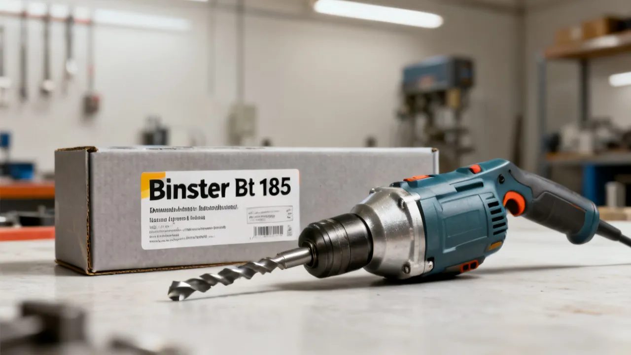
Binster Bt 185: Buyer’s Guide and Market Analysis
Binster Bt 185 is a specific industrial model people look up for procurement decisions, compatibility planning, and performance expectations. This guide explains, in an objective way, what buyers typically evaluate—specs, supplier reliability, documentation, and risk controls—so you can compare offerings and choose confidently based on verified information.

Posic Ebserh: How to Understand Your Options
Posic Ebserh helps people navigate healthcare-related planning and service access with clarity. This guide explains the core meaning and context behind the terms, then offers an objective framework for evaluating programs, responsibilities, and practical next steps. It also highlights what to prepare before contacting a supplier or healthcare coordinator, using neutral criteria and local sensitivities.

Using NotebookLM Effectively for Smarter Knowledge Work
This guide explains how NotebookLM can support structured note-taking and efficient knowledge work, from organizing sources to improving retrieval and writing workflows. Background context covers what NotebookLM is, why notebook-style systems matter, and how professionals commonly evaluate accuracy, privacy, and reliability when working with AI-assisted research tools.
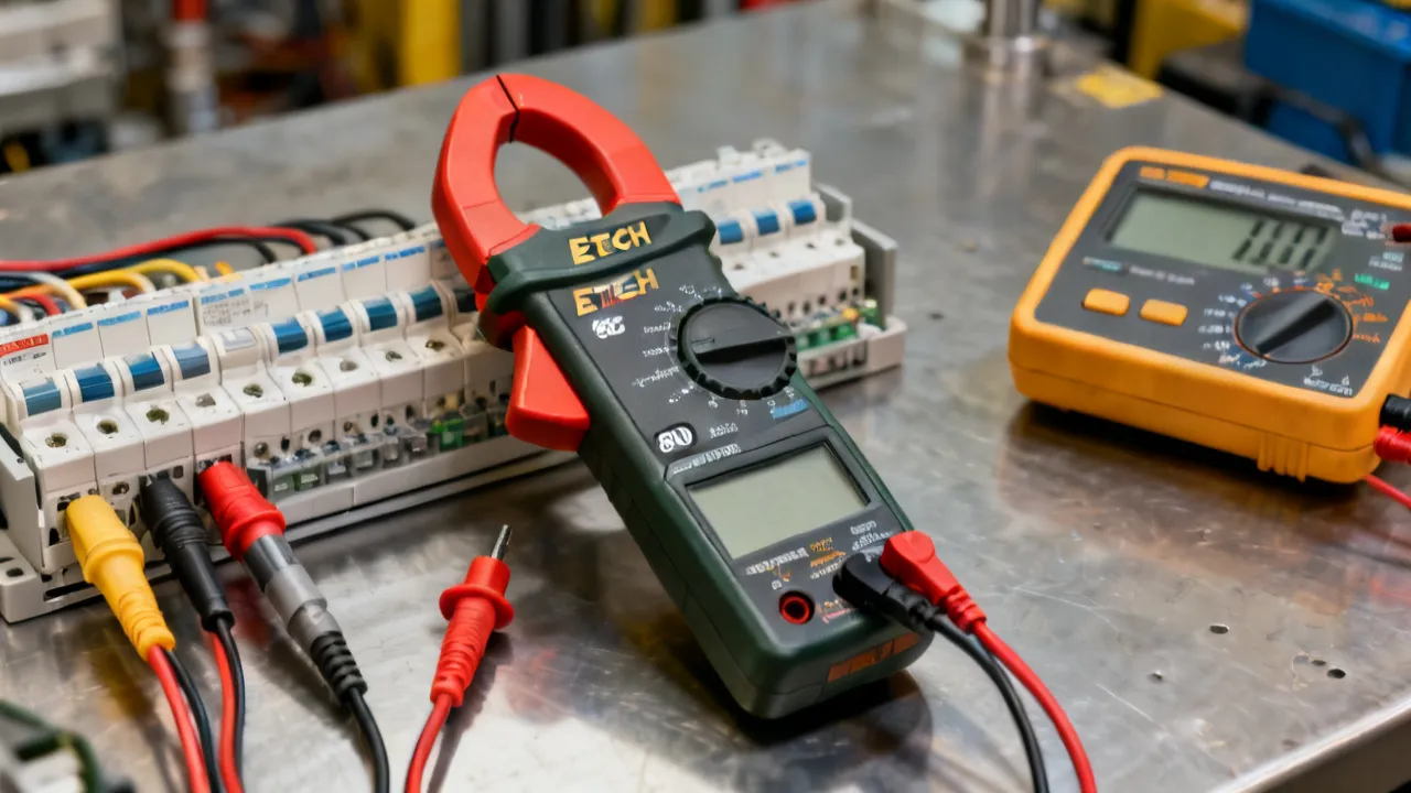
Extech EX800: A Practical Measurement Guide
This guide explains how to evaluate and use the Extech EX800 series of clamp meters for electrical troubleshooting, maintenance, and current measurement. The EX800 designation refers to a family of Extech instruments whose exact capabilities vary by model, so users should confirm the model number, measurement category, jaw rating, and manual before testing. The article covers operating principles, safety, accuracy, maintenance, selection criteria, and common questions.
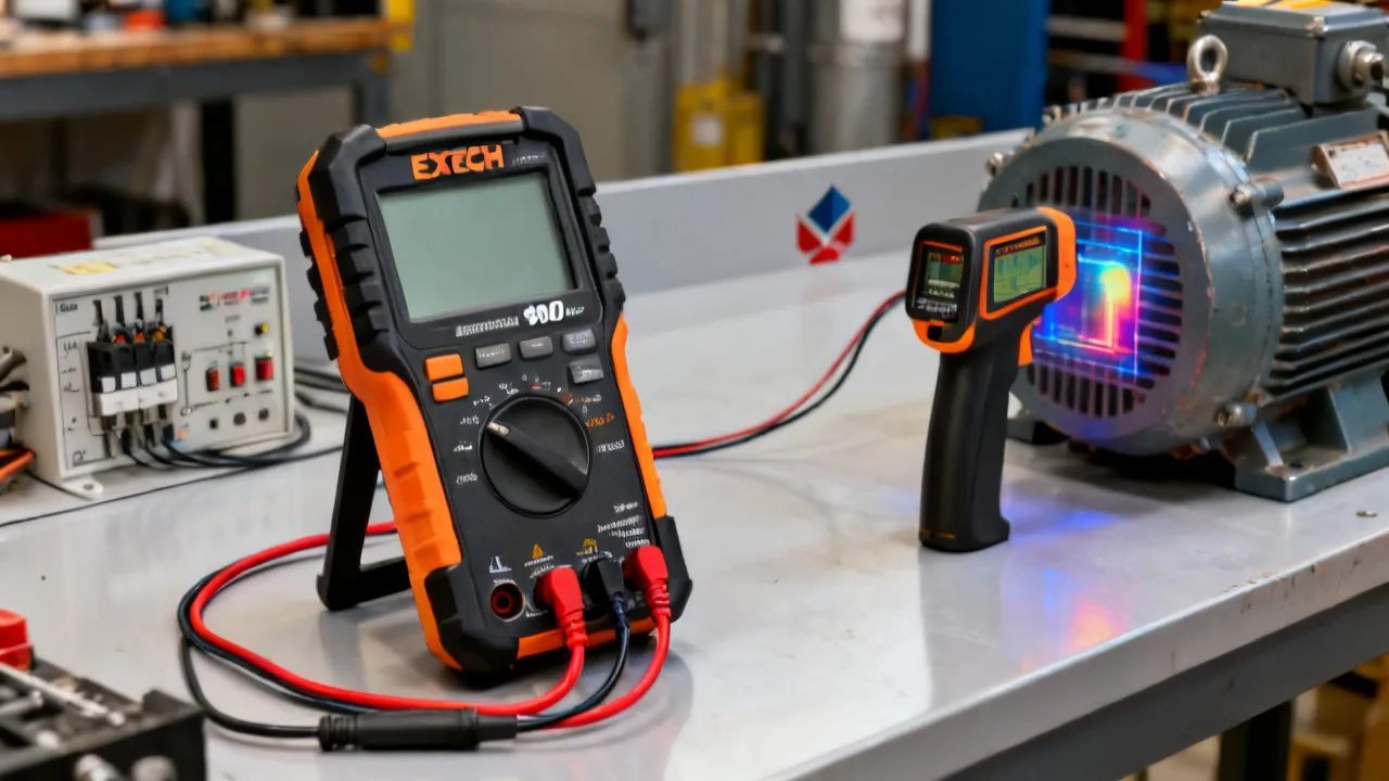
Extech EX900: A Practical Measurement Guide
This guide explains how the Extech EX900 can support electrical testing, troubleshooting, and temperature checks when used within its rated limits. The instrument is an industrial digital multimeter associated with functions such as voltage, current, resistance, continuity, frequency, capacitance, and infrared temperature measurement, depending on configuration and documentation. Its usefulness depends on correct lead placement, category ratings, environmental conditions, calibration status, and safe measurement procedures rather than on the number of available functions alone.